Vibration
Vibration on rolling stand bearings, gearboxes, drive motors, couplings, spindle assemblies, and roller-table drives can reveal changes in rotating equipment behavior. Measurement location and machine speed matter when comparing readings.
Condition monitoring gives steel producers a clearer view of the operating condition of rolling mill equipment while production is underway. By collecting relevant measurements and interpreting them in the context of machine identity, time, load, speed, and operating mode, plant teams can identify changes that warrant investigation before they become unplanned interruptions.
Contact MetalProcessCondition monitoring gives steel producers a clearer view of the operating condition of rolling mill equipment while production is underway. By collecting relevant measurements and interpreting them in the context of machine identity, time, load, speed, and operating mode, plant teams can identify changes that warrant investigation before they become unplanned interruptions.
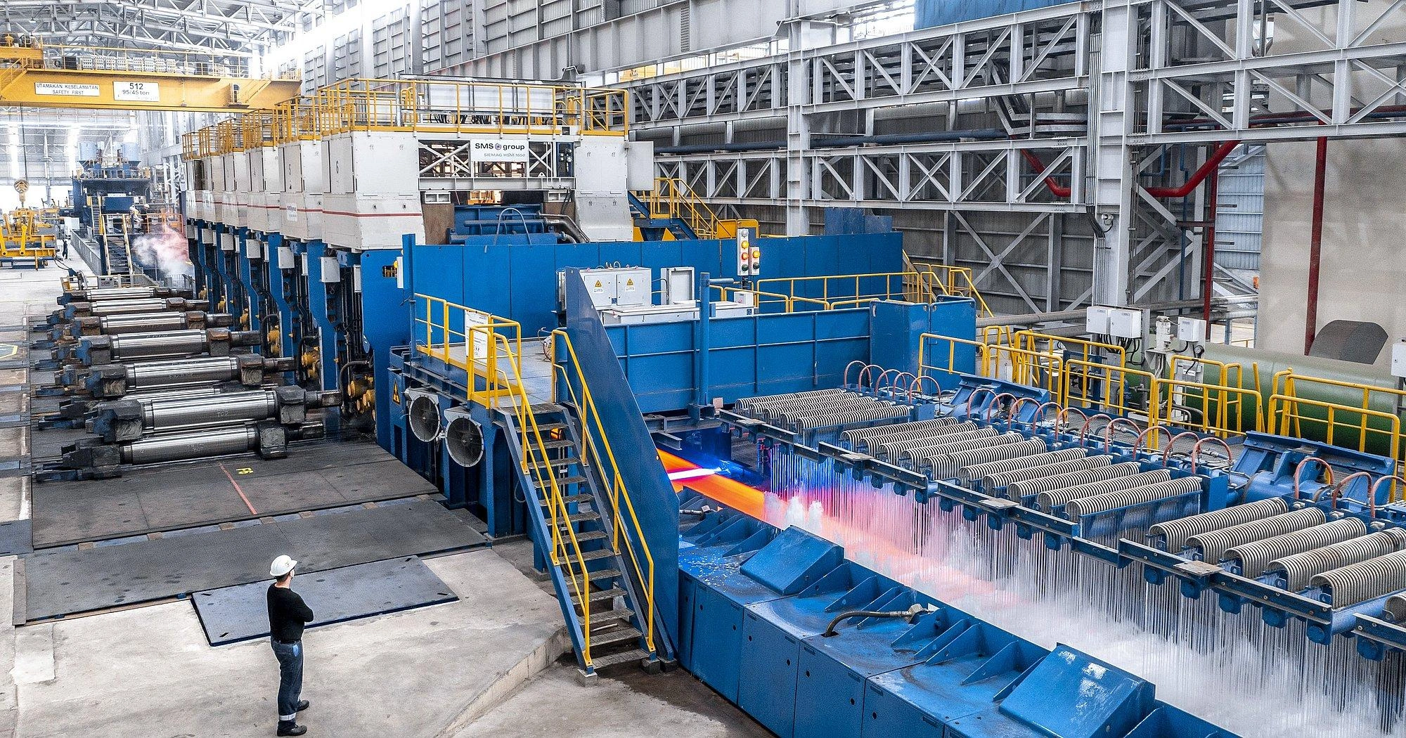
In hot and cold rolling operations, critical assets include work-roll and backup-roll bearings, mill stand drives, gearboxes, motors, couplings, hydraulic power units, lubrication systems, cooling-water circuits, and roller tables. These assets operate under changing loads, vibration, heat, scale, water, and demanding production schedules. A useful monitoring program accounts for those conditions instead of treating every sensor reading as an isolated number.
The right measurement plan starts with the equipment and failure or process condition the plant needs to understand. Sensor selection, mounting location, measurement range, sampling interval, and maintenance access should be defined for each monitoring point.
Vibration on rolling stand bearings, gearboxes, drive motors, couplings, spindle assemblies, and roller-table drives can reveal changes in rotating equipment behavior. Measurement location and machine speed matter when comparing readings.
Temperature at bearing housings, motor frames, gearbox lubrication circuits, hydraulic oil reservoirs, and electrical cabinets helps identify thermal changes. Interpret each value against equipment specifications and the current operating state.
Pressure and flow measurements on hydraulic power packs, lubrication skids, and cooling-water circuits help teams assess whether supporting systems are delivering the conditions required by the mill.
Electrical measurements such as motor current, voltage, and power can add context to drive loading and equipment behavior. Changes should be interpreted alongside speed, product schedule, and process demand.
Visual and environmental observations can help identify oil leakage, water ingress, scale accumulation, abnormal surface conditions, cabinet contamination, or unusually hot areas. Camera placement and environmental limits must be considered.
A monitoring design may combine permanently installed sensors with periodic measurements from portable vibration analyzers, thermal cameras, or inspection instruments. Permanent monitoring can support continuous trending at critical or hard-to-access points. Portable inspections can extend coverage where continuous instrumentation is not justified. The choice should reflect risk, access, operating exposure, and the level of diagnostic detail required.
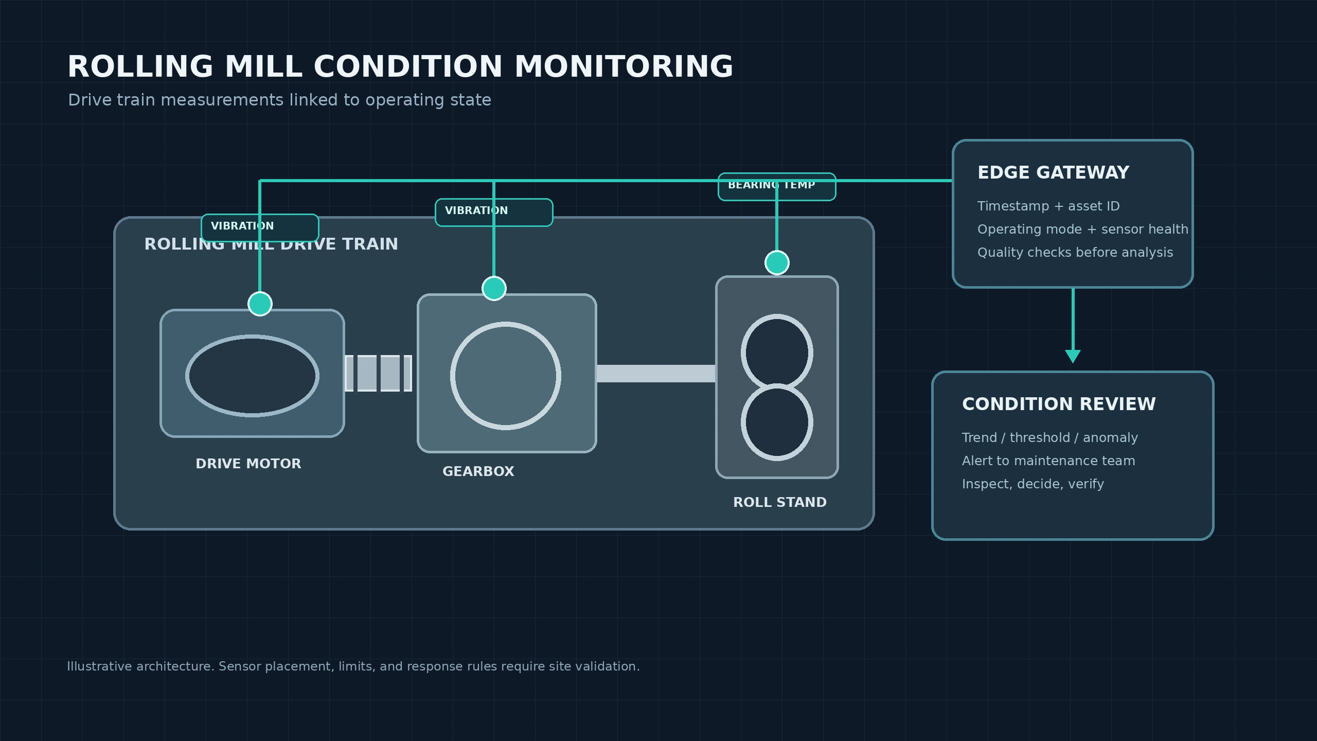
This illustration shows vibration and bearing-temperature monitoring points across a rolling mill drive train, including the motor, gearbox, and roll stand. It emphasizes the need to connect sensor readings to equipment identity and operating context before an alert is reviewed by maintenance personnel.
A condition reading becomes useful when the system can associate it with the correct asset and production state. Each record should carry, where available, an equipment identifier, sensor identifier, timestamp, engineering unit, operating mode, and sensor-health status. For a rolling stand, relevant context may include line speed, rolling force or load, product dimensions, pass or stand number, and whether the equipment is accelerating, running steadily, changing product, or stopped.
Context helps reliability engineers distinguish a genuine change from a normal response to a different operating condition. A vibration increase during a change in speed, for example, should not be assessed in the same way as a persistent increase under a comparable load and speed. Temperature trends may also need to account for startup, cooling conditions, ambient temperature, and recent maintenance.
Industrial Internet of Things (IoT) connectivity can bring sensor data from field devices and condition-monitoring instruments to an edge gateway or plant server. The data path should preserve timestamps, units, asset associations, and quality flags. Where connectivity is intermittent, the design should define local buffering, delayed transmission, duplicate handling, and how missing intervals are shown to users.
Equipment identifier
Sensor identifier
Timestamp
Engineering unit
Operating mode
Sensor-health status
Condition analysis can begin with engineering limits and established operating baselines. Thresholds are appropriate when equipment limits or operating procedures define a clear boundary. Trend analysis helps identify gradual changes over time. Artificial Intelligence (AI) and machine-learning methods may add anomaly detection when representative operating data is available and the expected behavior can be established with sufficient confidence.
Thresholds are appropriate when equipment limits or operating procedures define a clear boundary.
Trend analysis helps identify gradual changes over time.
Artificial Intelligence (AI) and machine-learning methods may add anomaly detection when representative operating data is available and the expected behavior can be established with sufficient confidence.
A learned anomaly score is not, by itself, proof of a fault. Models can generate false alerts when production conditions change, sensors drift, data is incomplete, or an operating mode is not represented in the baseline. Teams should review the measurements, confirm sensor health, compare like-for-like operating conditions, and document the reason for accepting or dismissing an alert.
A practical condition-monitoring workflow routes an alert to the responsible reliability engineer or maintenance supervisor with the asset, measurement, timestamp, trend, operating context, and reason for the alert.
Review the evidence.
Plan an inspection.
Compare readings with a known-good baseline.
Record the finding in the maintenance process.
Condition monitoring supports maintenance decisions; it does not replace inspection, engineering judgment, or required equipment protection.
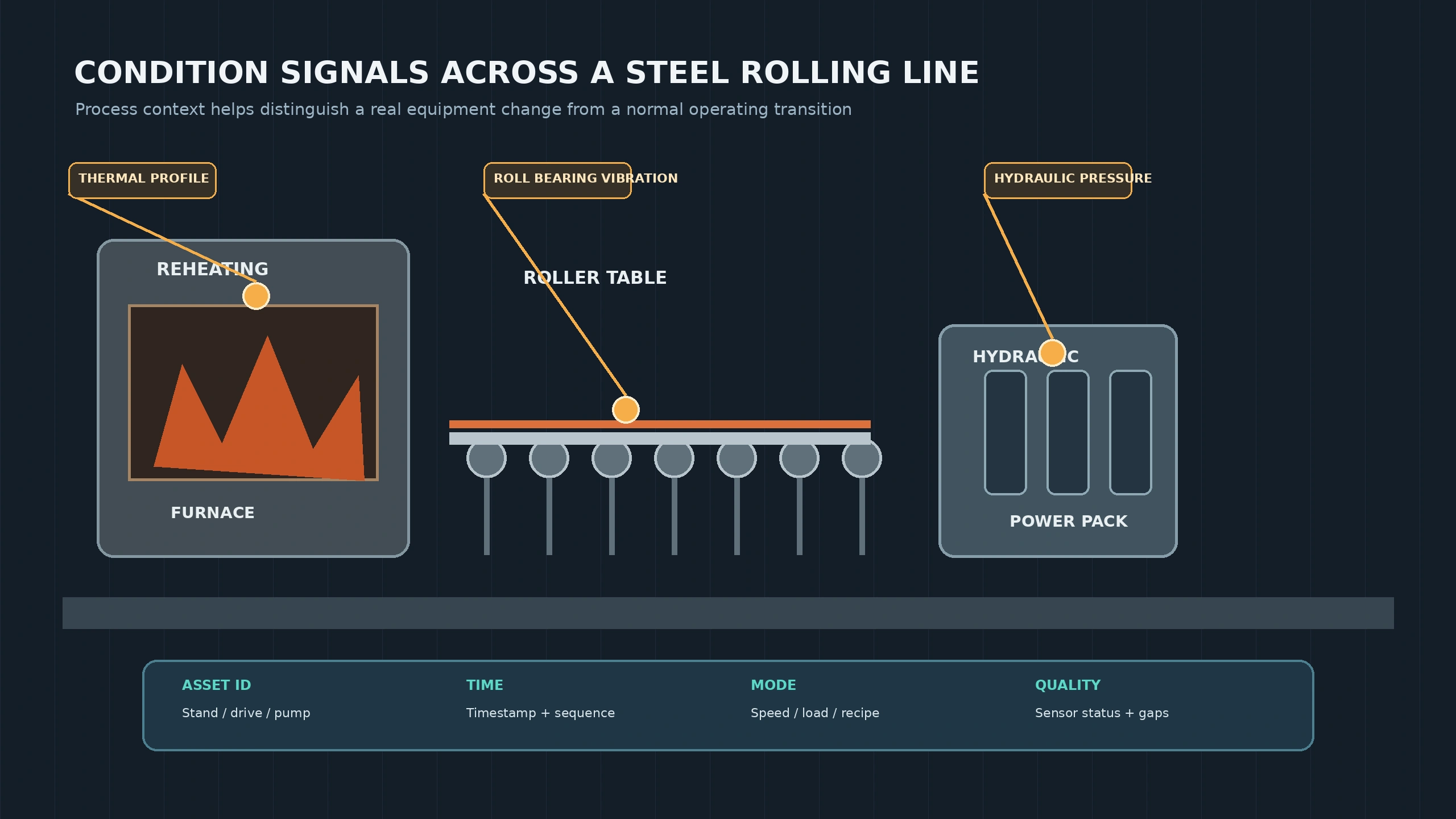
This illustration maps condition signals across a steel rolling line, including furnace thermal conditions, roller-table vibration, and hydraulic power-pack pressure. Its key takeaway is that measurements should be interpreted with asset identity, timestamps, operating mode, and sensor quality.
Condition data is more valuable when it can be reviewed alongside equipment history and maintenance records. Depending on the plant architecture, integration may involve a computerized maintenance management system (CMMS), manufacturing execution system (MES), supervisory control and data acquisition (SCADA) platform, distributed control system (DCS), or historian. The interface should define asset identifiers, event types, timestamps, units, alarm priorities, acknowledgment behavior, and ownership of records.
Computerized maintenance management system.
Manufacturing execution system.
Supervisory control and data acquisition platform.
Distributed control system.
Equipment history and condition data records.
For example, a sustained change in a rolling stand gearbox vibration trend could create a condition-review notification for the reliability team. After checking the trend against speed and load, the team may request an inspection during a planned operating window. The inspection result, corrective work, and post-maintenance measurements can then be associated with the original condition event. This closes the loop between sensing, review, maintenance action, and verification.
Where a monitoring platform is connected to control equipment, the boundary between advice and control must remain explicit. Any control action requires a defined authorization path, equipment-specific operating limits, appropriate interlocks and protective functions, and confirmation that the commanded state was achieved. AI-generated recommendations should not bypass validated mill controls or established safety procedures.
A pilot should test whether the selected measurements and alert logic provide actionable information under representative production conditions. Establish a baseline before installation or activation, and include normal operation, product changes, startup and shutdown, planned maintenance, and known data-quality problems where practical.
Alert usefulness: the proportion of alerts that lead to a justified inspection, maintenance review, or documented operational decision.
Detection delay: the time between the first measurable change and the alert reaching the responsible user.
False-alert and missed-event review: alerts that do not correspond to a confirmed condition, and known events that the monitoring design did not identify.
Data completeness: missing readings, delayed events, timestamp alignment, duplicate records, and sensor-health exceptions.
Calibration and maintenance effort: calibration frequency, sensor replacement, mounting checks, gateway maintenance, and time spent validating readings.
Follow-up verification: whether inspection findings and post-maintenance measurements confirm the suspected condition or show that the issue was resolved.
Compare results with the plant's existing inspection and maintenance process. Document equipment coverage, operating conditions, known blind spots, alert rules, model versions where applicable, and the people responsible for review. Expand only when the pilot demonstrates repeatable value and the site has a sustainable process for maintaining sensors, reviewing alerts, and acting on confirmed findings.
MetalProcess approaches condition monitoring as a connected sensing and decision workflow for metal forming and rolling environments. The sensing layer captures equipment and process measurements. IoT software associates those measurements with assets and operating context. AI-supported analysis can help identify trends or deviations for review, while responsible plant personnel retain authority over maintenance decisions and any operational response.
The implementation depends on the selected equipment, available instrumentation, network conditions, data quality, and integration requirements. A requirements discussion should identify the assets to monitor, the measurements needed, existing control and maintenance systems, deployment constraints, and the evidence required to evaluate a pilot. Specific hardware compatibility, integrations, and operating capabilities should be confirmed against the plant's actual environment before deployment.
Start with the equipment where an unexpected condition has the greatest operational consequence. MetalProcess can work with your team to define a monitoring scope, identify required measurements and data sources, and establish pilot evaluation criteria for your metal forming and rolling operation.